Most of the designers, have dealt with isometric projections in some moment of their careers. Very useful if one wants to represent industrial products in a user manual or to explain the functionality of a mechanism.
In this tutorial, I’ll explain how to approach this kind of axonometry in an easy way, using Adobe Illustrator.
The math behind an isometric projection
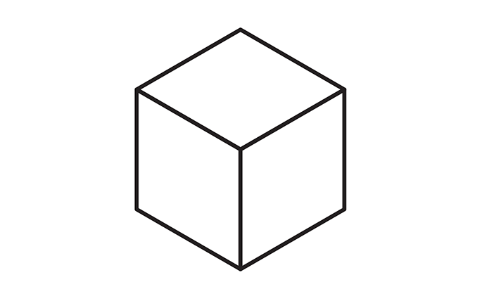
First of all, it would be great to understand the mathematical relations that a isometric projection has. Let’s analyze the next projection of a cube with a side of value a:

Looking at the previous projection, we can conclude:
- All sides of the projection have the same length (a). This is due to the fact that this kind of projection has the same scale in the three axes.
- The projection is formed with three identical rhombus rotated 120º one of each other, with internal angles of 60º (β) and 120º (θ).
- The projection is formed with six identical equilateral triangles.
- The value represented by h is the altitude of the equilateral triangles.
- As the altitude of an equilateral triangle divides its base in two identical segments, each of these segments has a length of a/2.
Analyzed these conclusions, applying the Pythagorean theorem, we can assure:
 from which it is derived that:
 therefore:
 and it can be concluded that:
 and:
and:

Transformation of each plane
Let’s analyze then the transformations that should be applied to each plane to create the projections:

Building the side view (SV)
It is needed to multiply the width by the square root of three divided by two. Namely, multiply the width by 0,866025, ergo, reduce the width in an 86,6025% of its size. After this, it is needed to skew vertically the plane 30º.
Building the front view (FV)
As with the SV plane, it is needed to reduce the width in an 86,6025% of its size, but after that, it is needed to skew the plane vertically -30º.
Building the top view (TV)
This is the most complicated transformation. To understand it, it is necessary to know that in a square it is fulfilled that its diagonals are equal to the square root of two multiplied by one of its sides (easily demonstrable using the Pythagorean theorem). Having this clear, I’m going to explain the transformations.
It is needed to rotate -45º the plane and then modifying its width and height. Let’s calculate first how much its height needs to be reduced and its width augmented. To achieve this, let’s divide the final sizes that we want by the original ones to obtain the percent necessary on each case. Let’s start with the width:

That is to say, it is needed to augment the width of the figure after the rotation 122,4745%. Let’s do the same with the height:

Therefore, it is needed to reduce the height 70,7107%.
Creating an isometric cube
To check the maths, let’s to create an isometric cube. Let’s create a square and duplicate it twice, these will be the three shapes that will be used to create each one of the projections.
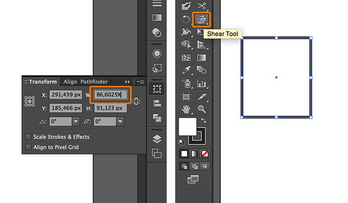
Let’s start with the side view. Select one of the squares, go to the Transform window, set the width (W) in 86,6025% and press Enter. After this, select the Shear tool and either double-click on its icon or with the ALT key pressed, click on the square.
You’ll see a window with the distortion options. In this window, set the Shear Angle in 30º and check that the Axis value is set as Vertical:
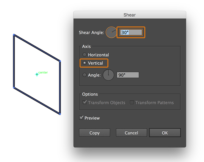
Press OK and the side view will be ready.
With the front view the process is the same as with the side view. The only difference is that the Shear Angle should be -30º.
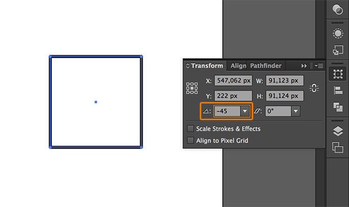
So, the next shape is the top view. Select the third square, go to the Transform window, set the rotation angle in -45º and press Enter:
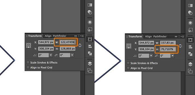
Now, you should modify the width and height of the resulted shape. Go to the Transform window, set the width (W) in 122,4745% and the height in 70,7107%:
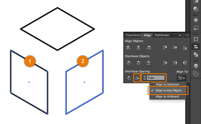
The three shapes are ready, you just need to align them properly. With the SHIFT key pressed, select the side view1 and the front view2. Then, go to the Transform window, select the Align to Key Object option, set the distribution value in 0 and click on Horizontal Distribute Space:
To align the shapes vertically, just hit on the proper icon in the Align objects section.
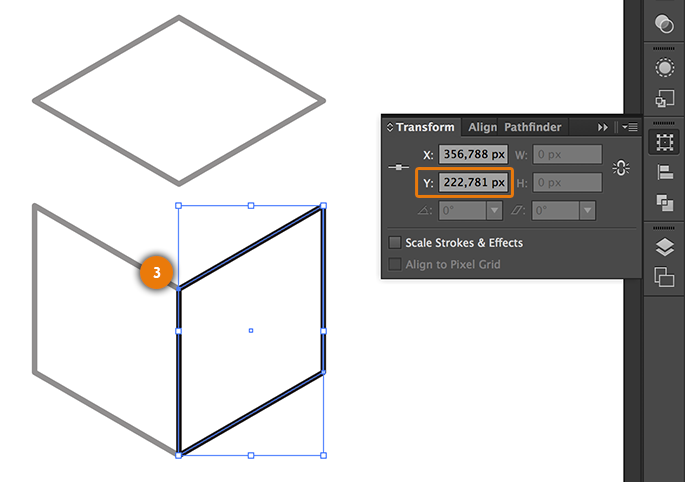
To join the top view with the rest of the figure it is needed to copy a value. Select either the side or front view and with the Direct Selection tool (you can select this tool pressing the key A) click on the indicated node3 and copy the y coordinates hitting CTRL + C on Windows or ⌘ + C on MacOS.
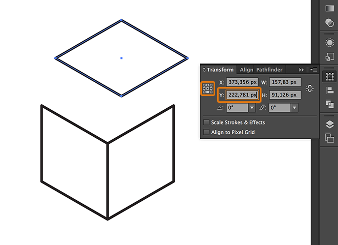
Now, select the top view, go to the Transform window, check the central-bottom reference point and paste in the Y coordinates field the value in the clipboard, pressing CTRL + V on Windows or ⌘ + V on MacOS:
And finally, to align the top view with the side or front view, just select the top view, select one of the remaining shapes with the SHIFT key pressed, click again on the same shape to set the align mode as Align to Key Object and finally click on the Horizontal Align Left icon.
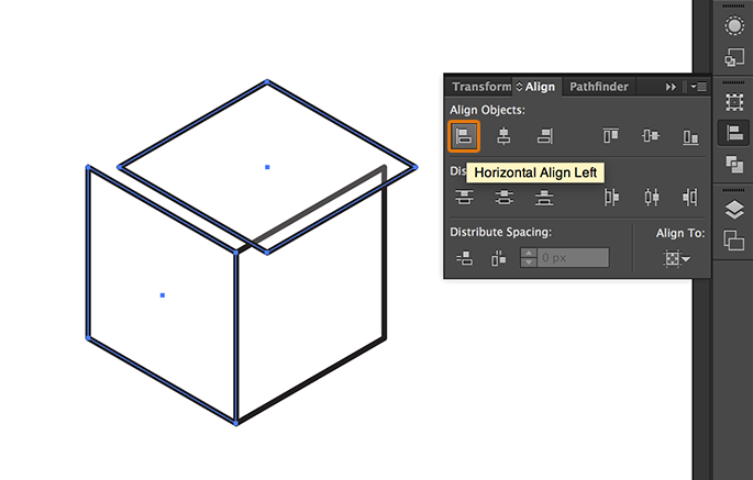
The result will be the next one, a perfectly projected isometric cube:
Knowing this technique, you can face more complicated figures. For example, having the next views:

You can generate all the needed pieces to create the projections with the right perspective using the method described in this tutorial.

And manage to create a figure with a medium complexity in a short time:

I hope you have found this tutorial helpful.

 (5 votes, average: 4.20 Out Of 5)
It is possible to insert code fragments between <pre></pre> tags and HTML or XML code between <xmp></xmp> tags.